This is a tutorial for the setup and configuration required when adding a FPV Gimbal to a Multirotor.

Seem like too much work? The store sells a selection of Fully Pre-Built Gimbal Drones!
Steps:
Joshua Bardwell made a video on adding a servo to a FPV drone, if you prefer that format follow his video for the portion of this tutorial related to servo control setup. For iNav setup, reference this video.
***If using TBS Crossfire or another receiver with ability to output an individual PWM signal you can just use an unused output pin as a PWM channel output to control the servo and skip the steps related to Betaflight setup, for example setting the 3rd output map to “CH7” will output a PWM signal for channel 7 on the 3rd output pad.
***If using ELRS, ensure that you are using a mode that allows the auxiliary channel controlling the gimbal to have full (or at least marginal) resolution.
- Locate an unused LED pin or unused motor output pin on your flight controller, as well as a source for 5V and ground, it is best to use an independent 5V regulator that is not being used by anything critical, but the flight controllers internal 5V regulator can work (use that at your own risk). These will be how you power and control the servo.
- Servo wire leads have the 5V in the center, and the ground and signal(PWM) wires on the sides with the signal(PWM) wire being white.
- You can choose to either use a male servo connector or to solder the servo leads directly onto the flight controller, some servos like the LDX-218 have a lead that has its own connector that plugs into the servo itself, for these you may want to just solder the lead to the flight controller since it has its own connector to the servo, the choice is yours.
- If you unplug the servo’s built-in connector, use a pair of tweezers to pull out the plug, do not just pull on the plug wires as this can damage them.
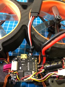
Plan on how you want to route wiring before soldering to the flight controller, and if using a capacitor consider where you want to place it. Ensure that the cables are long enough before cutting or soldering, check where the servo will sit on the frame and how it will be oriented to make sure your cables are long enough to reach.
Solder your servo leads or connector onto the flight controller pads, with the PWM wire going onto the unused LED pin or motor pad, the 5V to 5V, and ground to ground.
If using a capacitor (optional but recommended if not using an independent 5V regulator), solder the capacitor to the 5V and ground pads ensuring the correct orientation (most capacitors have a gray line with a “-“ on the negative side).
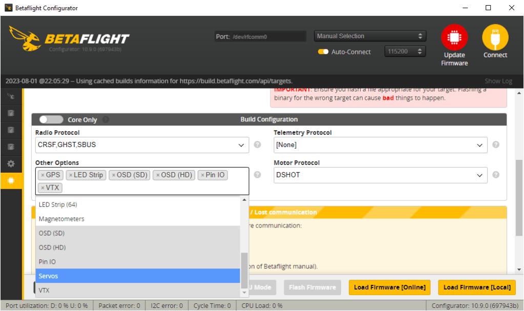
Go into Betaflight or iNav and follow the pictures bellow to set up your servo.
**If using Betaflight 4.4 or later, ensure that you have included the ‘Servos’ feature when flashing your FC, otherwise you won’t see the Servos tab in Betaflight.
Turn on ‘Servo Tilt” in configuration tab.
Assign an axillary channel to the Servo 1 in the Servos tab (may need ‘Expert Mode’ enabled to view Servos tab) and set MIN to 988 and MAX to 2012 for Servo 1.
Go into CLI, type ‘resource’. Hit Enter.
Find LED_STRIP 1 and take note of the ‘target’ that’s listed after it (for ‘LED_STRIP 1 A12’, the target would be A12), in the picture bellow the target is ‘B03’ but that will be different for each flight controller. Don’t forget the target, best to write it down.
Type ‘resource LED_STRIP 1 none’ (this will free the resource). Hit Enter.
Type ‘resource SERVO 1 yourTarget’ , for example: ‘resource SERVO 1 B03’. Hit Enter.
Type ‘save’. Hit Enter.

- Now it’s time to test servo control, using whichever auxiliary channel you assigned in the Servos tab. Plug in the servo, power the drone up, and move the assigned auxiliary channel from low to high and confirm that you have control of the servo.
**It is recommended that you re-tune your drone after installing the gimbal.
Now that this is done, you will want to follow the steps to:

3 thoughts on “Configuration and Setup for Adding a FPV Gimbal to a Multirotor”