This tutorial is for implementing an Open-Source Design by Medlin Drone.

Seem like too much work? The store sells a selection of Fully Pre-Built Gimbal Drones!
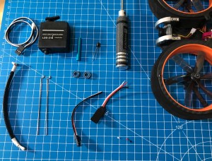
What You’ll Need:
Wow look at this long list… if only there were kits available… with components tested to ensure compatibility… the Medlin Drone Store sells kits, including full kits that come preassembled and configured.
- 3D Printed Gimbal Parts designed to fit your frame (Open-Source Designs by Medlin Drone).
- 1x Digital Metal Gear Servo LDX-218
- 1x Servo Horn 25T for LDX-218
- 1x Servo Horn Sleeve/Insert
- 2x Ball Bearings 10mm OD, 5mm ID, 4mm Thick
- 1x 30mm M3 Standoff 5mm OD
- 1x Servo Linkage Wire
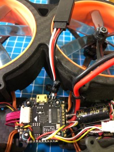
- 1x 100uF 16V Capacitor
- 1x 20mm M3 Screw
- 2x 5mm M3 Screws
- 4x 15mm M2/M3 Screws for mounting gimbal to frame
- 1x FPV Camera Wire Extensions (Optional, you may or may not need to extend your camera wires). For DJI FPV or Shark Byte you may need to move your VTX forward in the frame or use an extension cable. Camera extension cables available for Analog and DJI FPV at the Medlin Drone Store!
- 1x Servo Cable Extension (Optional, can cut off servo plug and solder directly)
- 1x Wire Shrouding (Optional, helps protect FPV camera wire)
- 1x Head Tracking Unit (Optional, recommended) – Pre-Built Head Tracker available at the Medlin Drone Store! Here’s a tutorial for Adding a Head Tracker to Your Setup.
- 1x PWM Output to Control Servo via an unused LED pin or motor output pin on your flight controller (instructions bellow) or via a receiver with ability to output an individual PWM signal on an unused output pin, such as TBS Crossfire.
Build Steps:
These are the general steps you will need to follow to add a servo gimbal to a FPV drone, via a Medlin Drone kit, the exact setup will vary from frame to frame and preference.
First you will need to do the Configuration and Setup for Adding a FPV Gimbal to a Multirotor


Installing the Basic FPV Gimbal
- Test servo control, using whichever auxiliary channel you assigned in the Servos tab. I recommend having the servo horn OFF the servo and using a smoke stopper for first plug in. THESE SERVOS CAN BREAK YOUR FINGERS please be careful. You won’t know which way the servo is currently oriented until you have control of it, it would be easy to break things including yourself if you don’t use cation for this step, take the servo horn off so that no matter which way the servo spins it will not damage anything. Once you have confirmed you have control of the servo you can move on to physical setup.
- Now is a good time to think about how you want to route your FPV camera wires, or extend them if you need to. This will vary from frame to frame.
- Insert servo into the gimbal base.
- Check that the servo is plugged in and mount the gimbal base onto the frame, you may need to have the top half of the gimbal disconnected to reach the front bolts.
- Insert the bearings into the bearing housing on the front of the gimbal base.
- Insert the M3 standoff into one side of the gimbals top half hinge, but only a little such that the hinge can still fit onto/over the bearing housing.


- Then line up the holes and press the standoff through the bearings and housing and through the other side of the hinge, there is a built-in stop so just press as far as it will go.
- Now screw a long (20mm+) M3 screw into the smaller hole on the side of the gimbal hinge and into the standoff, tighten until pretty snug. For the other side use a short M3 screw and gently snug.
- Check that your FPV camera wires reach the camera, aren’t being pulled on when the gimbal rotates, and aren’t interfering with the propellers.
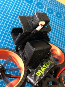
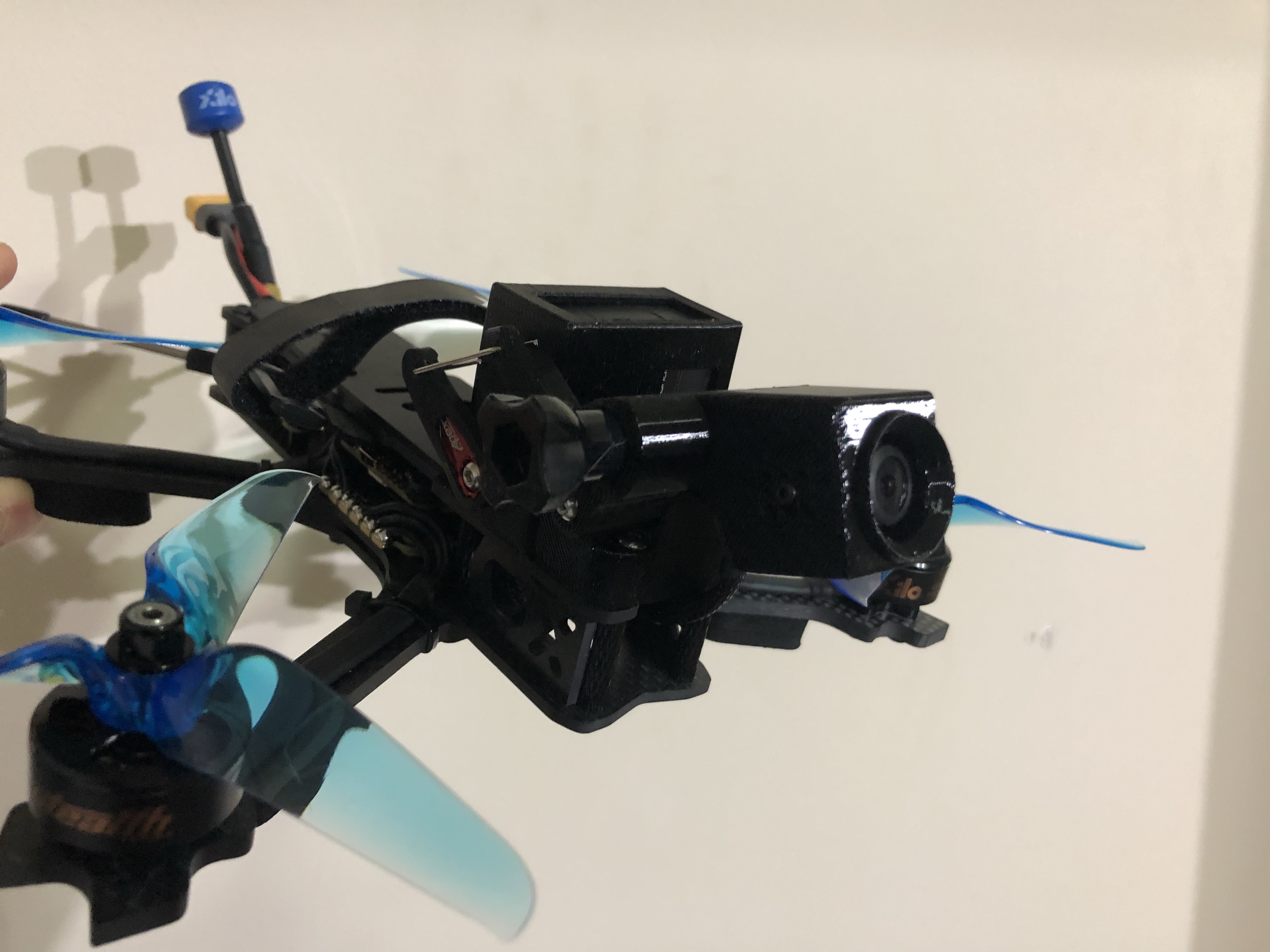
- Next is to set up the servo linkage, it is useful to think about how far up/down you want the gimbal to rotate and decide where to you would want the servo linkage to connect to the top half of the gimbal, this will most like require trial and error, here is one of my setups for reference.

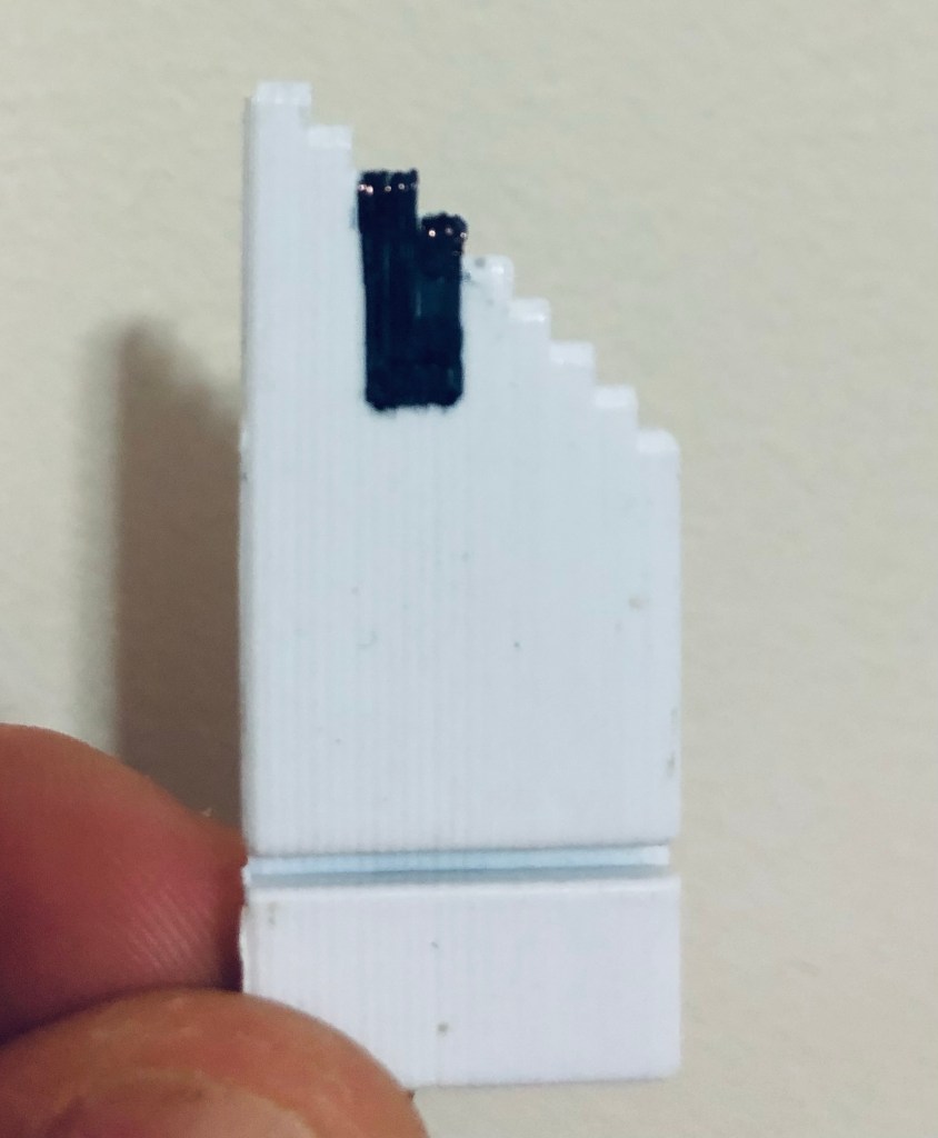
- I recommend using the Medlin Drone servo wire bending jig to bend the wire to the desired length. Make sure the servo wire is long enough to avoid the ‘weak triangle’ pictured bellow, this can cause the gimbal to not be sufficiently stiff in high uptilt position and is typically only an issue if the servo wire is too short and solved by increasing servo wire length.
- Clip off excess wire. I also recommend using a servo horn sleeve/insert to remove any free play in the linkage connection to the servo horn.


- Insert servo linkage wire into servo horn as shown in the picture bellow. If using servo horn sleeve/insert, use pliers as this may require some force.

- Poke the servo wire though the linkage connection tab, there is a premade hole it should fit through.
- With the servo horn OFF power on the drone and rotate the servo (via your transmitter, NOT by hand) all the way back/counterclockwise. This is where having control via a slider is useful, as described in the tutorial for adding a head tracker to your setup.
- Mount the servo horn in the furthest back position that you want the range of motion to be. It is secured with a short M3 bolt.
- Exercise caution at this stage, use your own judgment, Medlin Drone is not responsible for any broken parts or fingers. Double check that the servo and servo horn are in the correct position before powering on with the servo horn mounted.
- The gimbal will give a little with force but shouldn’t have slop/free play. Check that there is not slop in the linkage. Note that when a GoPro is mounted and tightened down it significantly stiffens the gimbal.
- Ensuring that your transmitter is on and has the channel controlling the servo in the same position as it was when you powered the drone off, carefully power on the drone and test the range of the gimbal.
- If the servo isn’t moving, try moving the input signal for the servo to both ends of travel.
- Once the gimbal is setup there isn’t as much need for caution, as it should maintain its current range of motion, but I still recommend respecting the servos power.
- Mount the FPV camera and connect the camera wires. Check that camera wires aren’t being strained during gimbal movement.
- Test that everything works and you are getting signal from your FPV camera to your VTX.
That’s it, if you haven’t already I recommend adding a head tracker to your setup and referencing the flight tips before your first flight. Happy flying, welcome to next level FPV!
Note: If/when you want to unplug the built-in plug on the front of the servo, I recommend carefully using tweezers to unplug it as pulling on the cable directly can damage it.

2 thoughts on “Add a Basic (Pushrod) FPV Gimbal to a Multirotor”