This is a rough account of the design progression of the Timing-Belt FPV Gimbal.
It doesn’t cover every hurdle or design revision, just some of the major points of progression.
First thoughts (Approx 6/15/22):
I have recently had my kits and designs get in front of more people at higher levels. This has provided me with a lot of useful feedback and also provided some additional motivation to optimize the system.
I was responding to an email discussing design considerations, and while spit balling alternate design ideas I thought of a ‘timing belt’, which didn’t strike me at first, but as I was looking it back over the idea grew on me. Tension in the belt could provide excellent stiffness, the movement between the servo and the gimbal would be perfectly consistent, and what if the pulley was just tight enough that it provided good stiffness, while ‘skipping’ under heavy load aka a hard crash (or perhaps use a tensioner system), and what if the gimbal had “hard stops” for its rotation, so that in theory the gimbal could ‘self-right’ itself with one full throw of the range….
With fine tuning of the tension and profile of the pullies and belt, this could allow very consistent performance and also be more durable/crash resistant than any of my previous design ideas.
I think this could be the ultimate solution, but it will need to be tested to know, will update soon.
UPDATE (Approx 7/5/22):
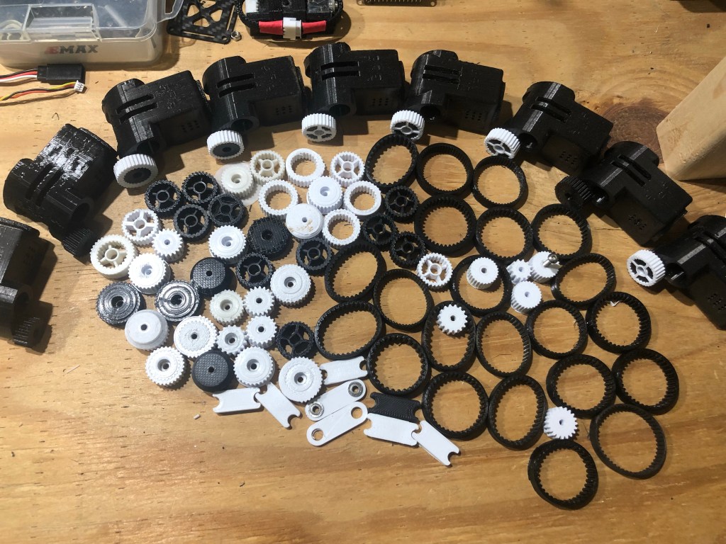
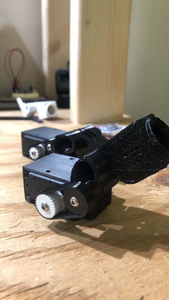
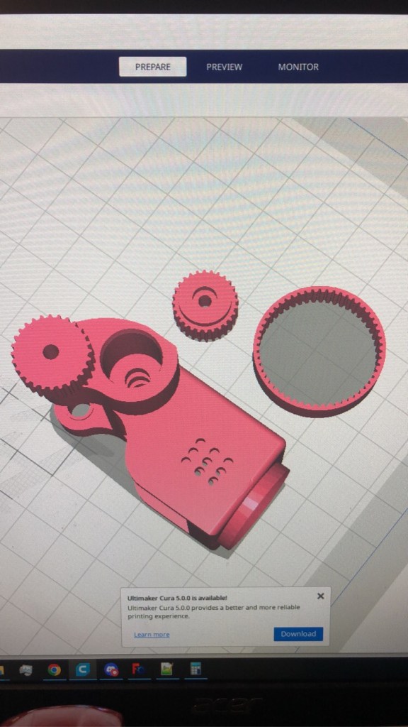
A lot of testing and development has occurred since I first conceived this, many iterations, many issues found, and lessons learned along the way. First, I iterated through different tooth and belt designs, all 3D printed, and was getting good results once I found the right combination. Also, experimented with ‘mixed material’ base/hinge designs, that used flexible and rigid materials. Then… I took it on a short trip to a flying location and the system had time to heat up in the summer sun.. suddenly the belt was loose, and the Universal Mount had bent towards the direction of the belt tension as the hinge/base warped. I was forced to realize the entire based needed to be rigid (this changed in the last stage of design iterations, as the “tension strut” mentioned later removed the need for a rigid base) and that it wasn’t going to be a simple all-printed solution, and so began my series of ‘hot car’ tests where I would leave a perfectly functioning gimbal (at room temp) in my car in the summer heat, and time and time again would find it suffered some sort of loss in the heat. Continued to iterate.
UPDATE (Appox 7/14/22):
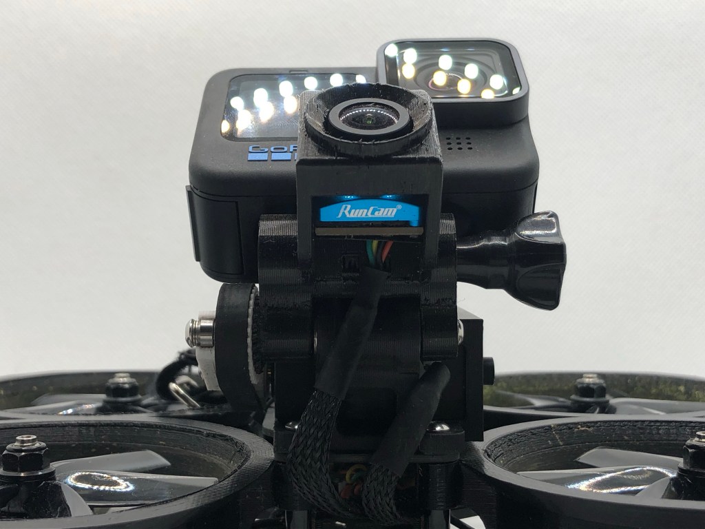
At this point I accepted that a 3D printed belt wasn’t going to be a viable solution, so I got some premade fiberglass reinforced GT2 belts (typically used for 3D printers) and created a design that used the GT2 tooth design, thinking it was probably good to use an ‘industry standard’ tooth design anyway, as it had already been rigorously tested. I was lucky to have Gab707 testing my gimbal prototypes and we were both seeing promise in the premade belt, superior stiffness and heat resistance. However, I still was failing the ‘hot car’ test, with the Universal Mount bending towards the direction of the belt tension as the hinge warped and in turn loosened the belt.
UPDATE (Appox 7/21/22):
I began to get discouraged about the viability of this, it was so finicky compared to the pushrod design, which handled heat variance/cycles without issue. The performance of the ‘timing belt’ design was so good, as long as it stayed at 72 degrees (Fahrenheit)… I started diving into different materials, learning about heat deformation and ‘glass transition’ temperatures for various materials compared to their baseline stiffness. And had some success trying materials with better heat deformation, but noticed that in time the constant tension of the belt would always overcome the hinge, especially with a few heat cycles.
UPDATE (Appox 8/8/22):
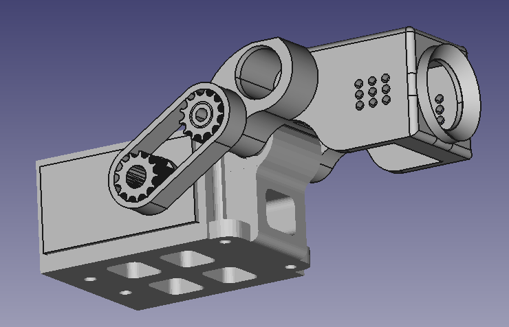
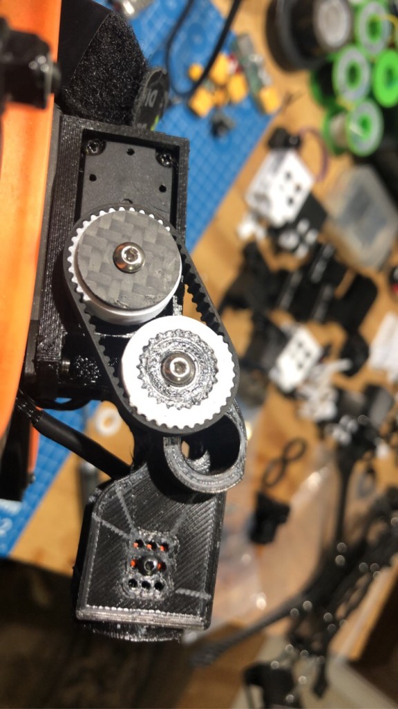
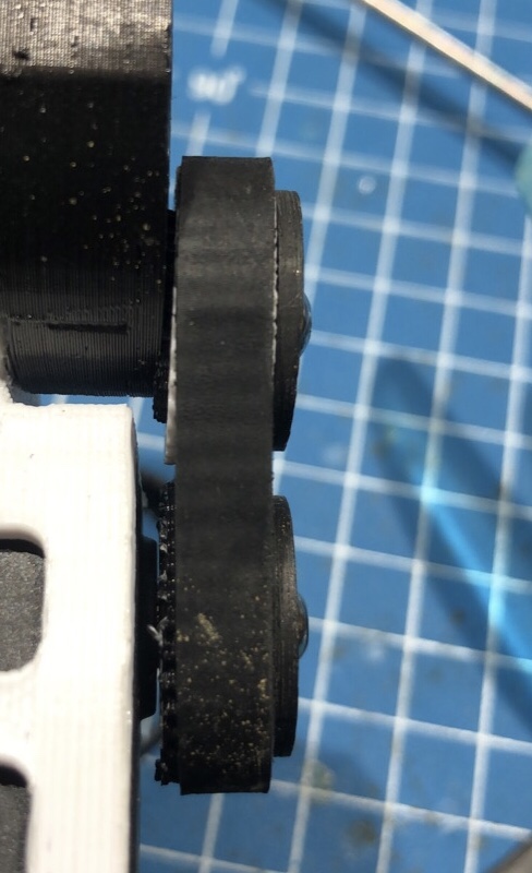
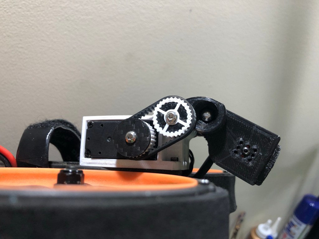
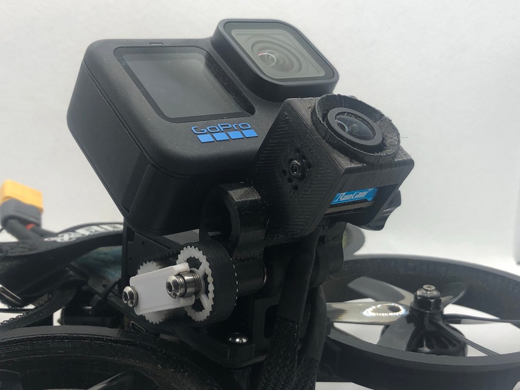
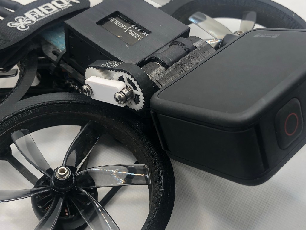
The constant tension creates two main ‘lever arms’ in the design, resulting from the belt’s tension on both pulley’s… I realized there was no way around it, that constant torque was going to affect the gimbal in heat cycles unless I countered the tension force. Thus, the ‘Tension Strut’ came to life, a strut containing bearings that would be at the end of both pullies and bear the force of the belt tension. This is technically a passive/reactive solution, as it only bears the force if there is some degree of deflection, but if it is the correct length that deflection can be too small to observe or matter. This was it, this is what took it from something that sounded good on paper to something that actually worked, Gab707 agreed, this was good.
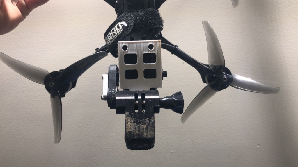
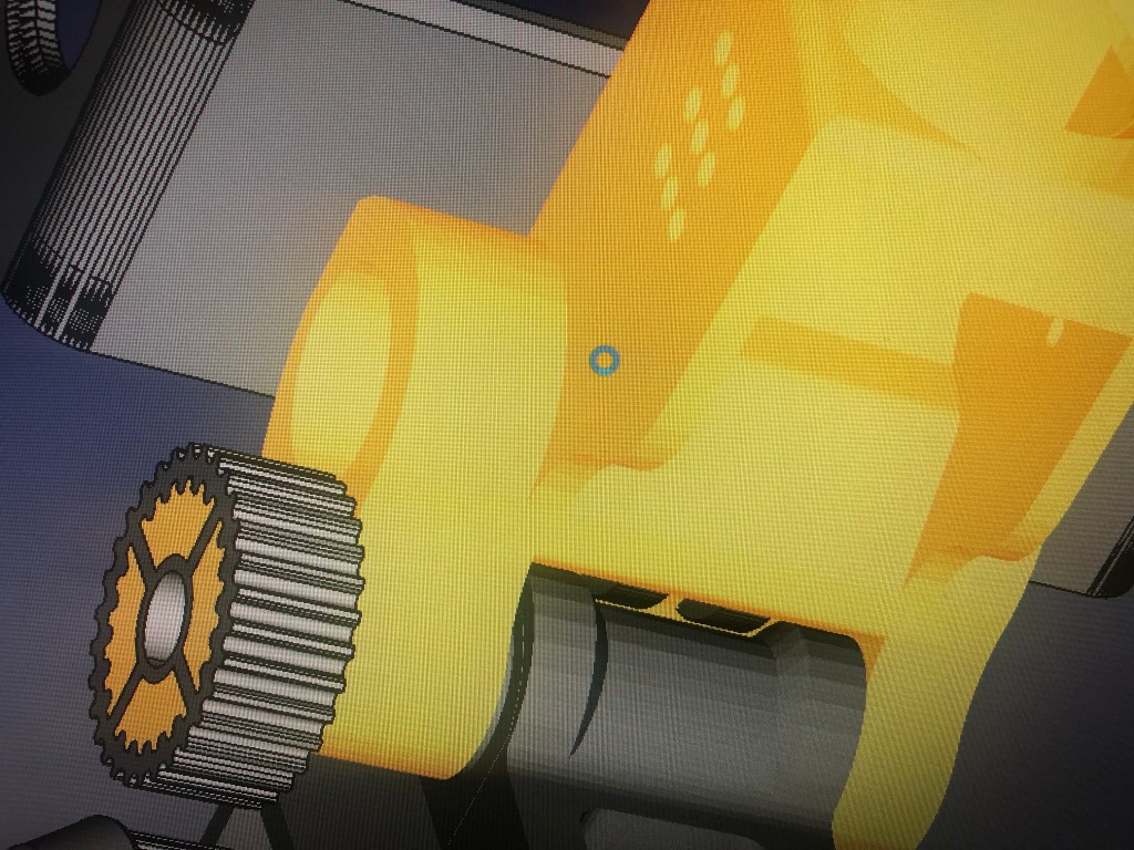
In the same swing I took another look at the design as a whole and realized that the TPU Universal Mount was bearing the force of the belt tension on its pulley, which over time and through heat cycles might compress and loosen the belt, hence the creation of the ‘Supported Sleeve’ pulley, that slips into the Universal Mount creating a strong interface between the two, while creating a rigid structure between the metal axle and the belt.
Also, Gab707 mentioned the hinge itself didn’t have much material, I agreed but noted that the current designs already have the ‘GoPro Tabs’ almost touching the bearing housing. Then it occurred to me, what if the bearing housing was just reinforced around the bearings themselves (where the material was currently the thinnest) but the rest of the housing remained unchanged, and then the ‘GoPro Tabs’ actually stuck out through the bottom of the Universal mount and rode inside the slot that was between the reinforcement material, hence the ‘Tab Slot’ was born, this was useful for my pushrod designs as well, as its basically ‘free strength’ for the gimbal.
UPDATE (Approx 10/1/22):
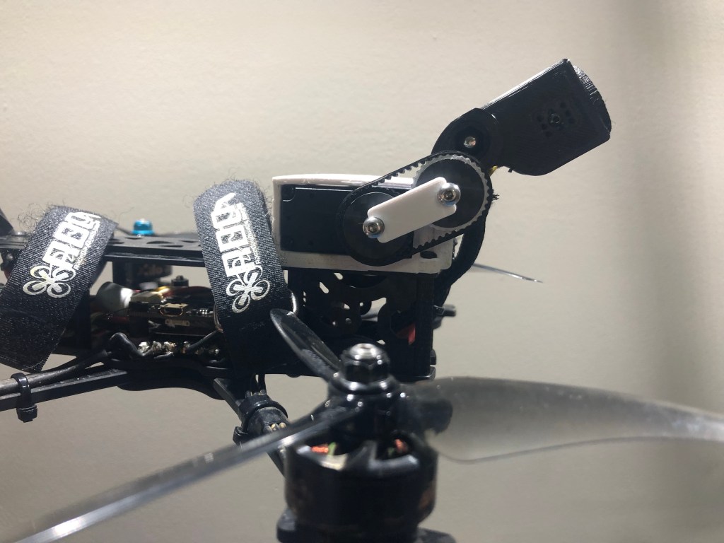
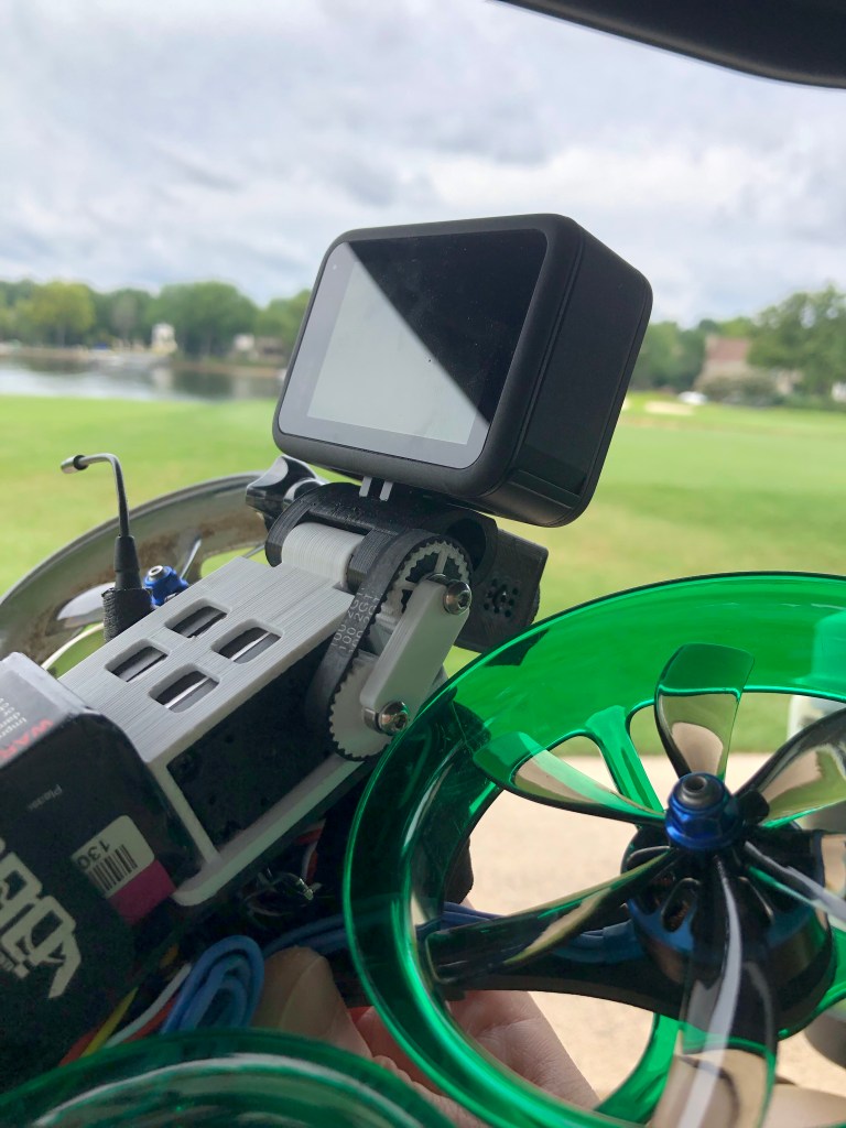
Have been busy with the store and with filming/flying, but I have converted my entire fleet to the ‘timing belt’ design and have been testing it in real-world scenarios including some brutally hot days, have made a few tweaks in the designs and have been experimenting with various materials, including some ‘engineering grade’ materials. I think it’s finally a verifiably good solution and ready to announce to the public. I didn’t want to announce it before making sure it was viable, and then have people excited about something that wasn’t going to work well. A lot of testing and headaches have come from this and especially having to keep it under the covers through all of that, truly an emotional rollercoaster, but I think it was worth it.
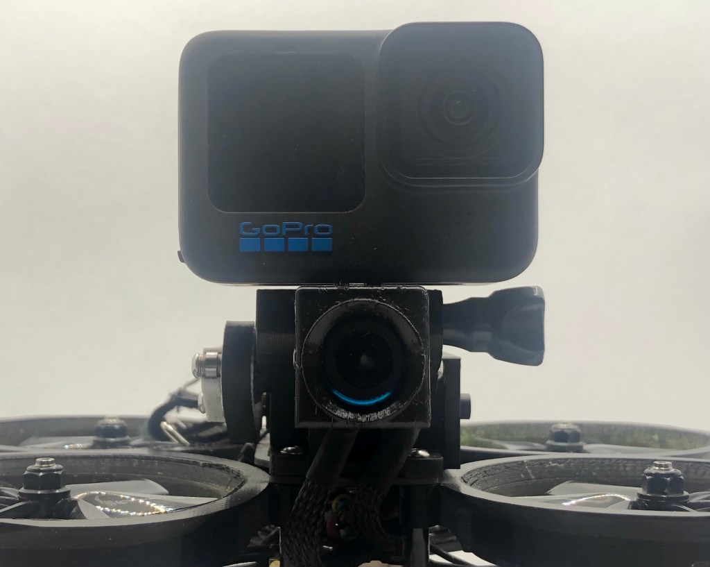
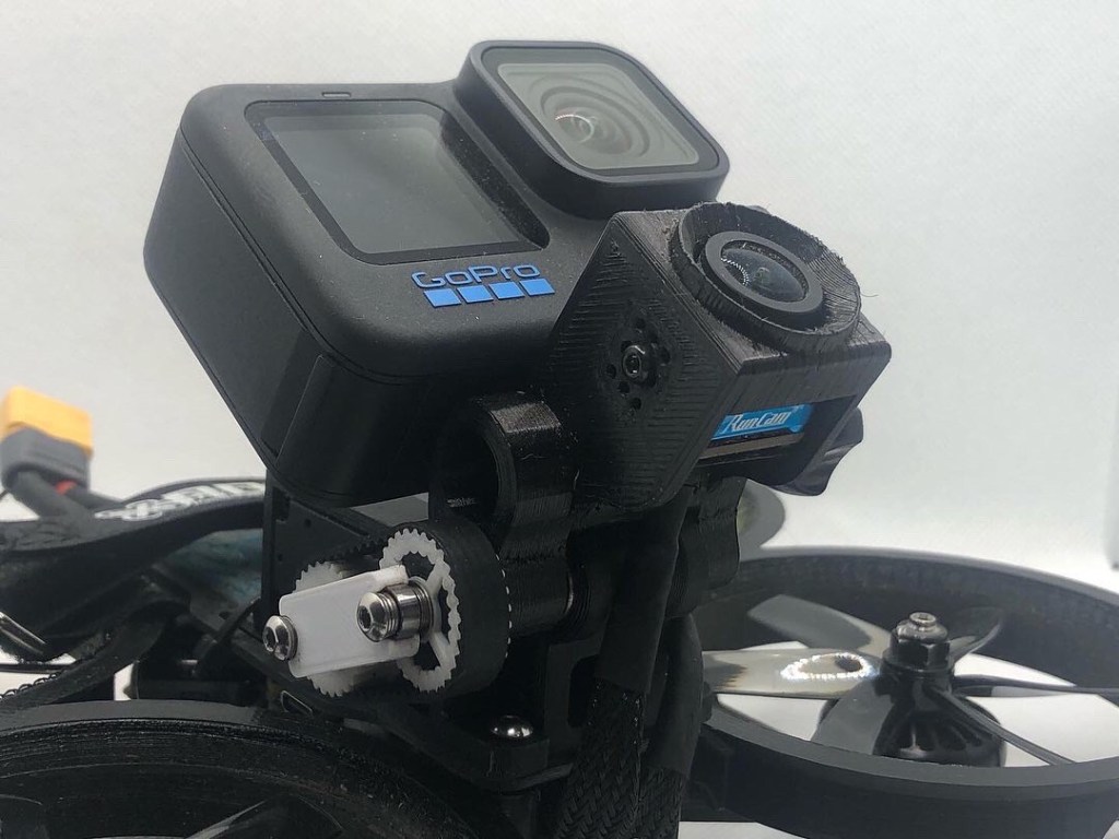
Something to note about the latest designs and premade belt is with the strength and stiffness does come with the loss of the “self-right” feature, as this will skip teeth in hard a crash but the tension/stiffness is higher than the early prototypes and the servo cannot skip the teeth back into position (you can just use your hands to skip it back into position, takes literally two seconds and is toolless, video on how to do that in the tutorial). This will be called the “Pro” gimbal as it is designed for professional use where stiffness and consistency are key above all else, while the pushrod design will be called the “Basic”. Currently, my plan is for the Pro designs to be closed source, I may change my mind on this, but I can’t “unrelease” the designs once I post them open source and I have spent so much time, energy, and headaches on this that I can’t bring myself to do it, at least yet. However, the base designs will be open source, meaning that you can swap a Pro gimbal from drone to drone if you have a 3D printer, the Pro bases are the shared with the Basic (pushrod) gimbals as well and the Basic gimbals are still getting improved along with the timing belt design with the things learned from the Pro gimbal development (such as the “Tab Slot” feature). Essentially, Medlin Drone will have free ‘Basic’ gimbal designs for anyone to use and implement and offer ‘Pro’ gimbals for serious use.

2 thoughts on “Timing Belt Linkage – The Ultimate Solution?”